System Overview
The transition from LiteTouch to this modern stack represents more than just a hardware swap; it is a complete change in how the infraestructure of the house. I moved from a single, central brain to a distributed network where every component is replaceable, standardized, and smart.
Recap: LiteTouch
Before I introduce the new components of the house, here a small recap of litetouch. If you want to know more about how litetouch worked you can check the electrical overview page.
Originally, the house relied on a Central Control Unit (CCU). You can think of this as a 40-year-old mainframe sitting in a dark closet. It was a "Command and Control" architecture:
- The Keypads: These weren were the switched; they acted as dumb buttons. When click they sent a raw electrical signal through cables back to the CCU.
- The Brain: The CCU received that signal, looked up a programmed "scene," and decided which lights to turn on.
- The Modules: Large, heavy dimmer racks that took orders from the brain. They did the heavy lifting of allowing electricity to flow.
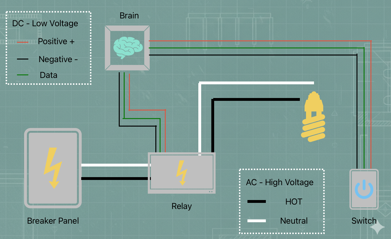
LiteTouch Diagram
In the old system, every button was physically tied to a central computer in a closet by a specific wire. When a button was pressed, it sent an electrical pulse down that wire. The central computer received that pulse, looked up what it was supposed to do, and then told a large dimmer/relay box to send power to the light bulb. If that one central computer was off or broken, the button press went nowhere.
Introducing the New Crew
Now, the house no longer runs on LiteTouch but rather a series of independent components that work with each other to turn the lights on and off. Instead of a proprietary "closed" system, these devices communicate using standard Wi-Fi and network protocols. To understad the new system, first I need to introduce the new parts running the show
Home Assistant (The Brain)
I am running Home Assistant as the central nervous system. Technically, it is an open-source automation platform that acts as a Local Server. It doesn't live in "the cloud"; it lives inside the house. It maintains a database of every light's status and runs the logic that tells the Shelly relays when to click.
Shelly Pro Relays (The Muscle)
These are industrial-grade switches mounted on DIN rails inside the main electrical boxes. Technically, these are ESP32-based smart relays. They are the bridge between the digital world and the high-voltage (120V) world. They connect to the house network via Wi-Fi or Ethernet and handle the actual heavy lifting of cutting power to the light bulbs.
ESP32-CYD (The Face)
The "Cheap Yellow Display" (CYD) is a small touchscreen powered by an ESP32 microcontroller. I use these to replace the old physical keypads. They run a custom interface that sends commands over the network. Instead of a physical button click, they send a digital "message" saying, "Someone touched the Kitchen button."
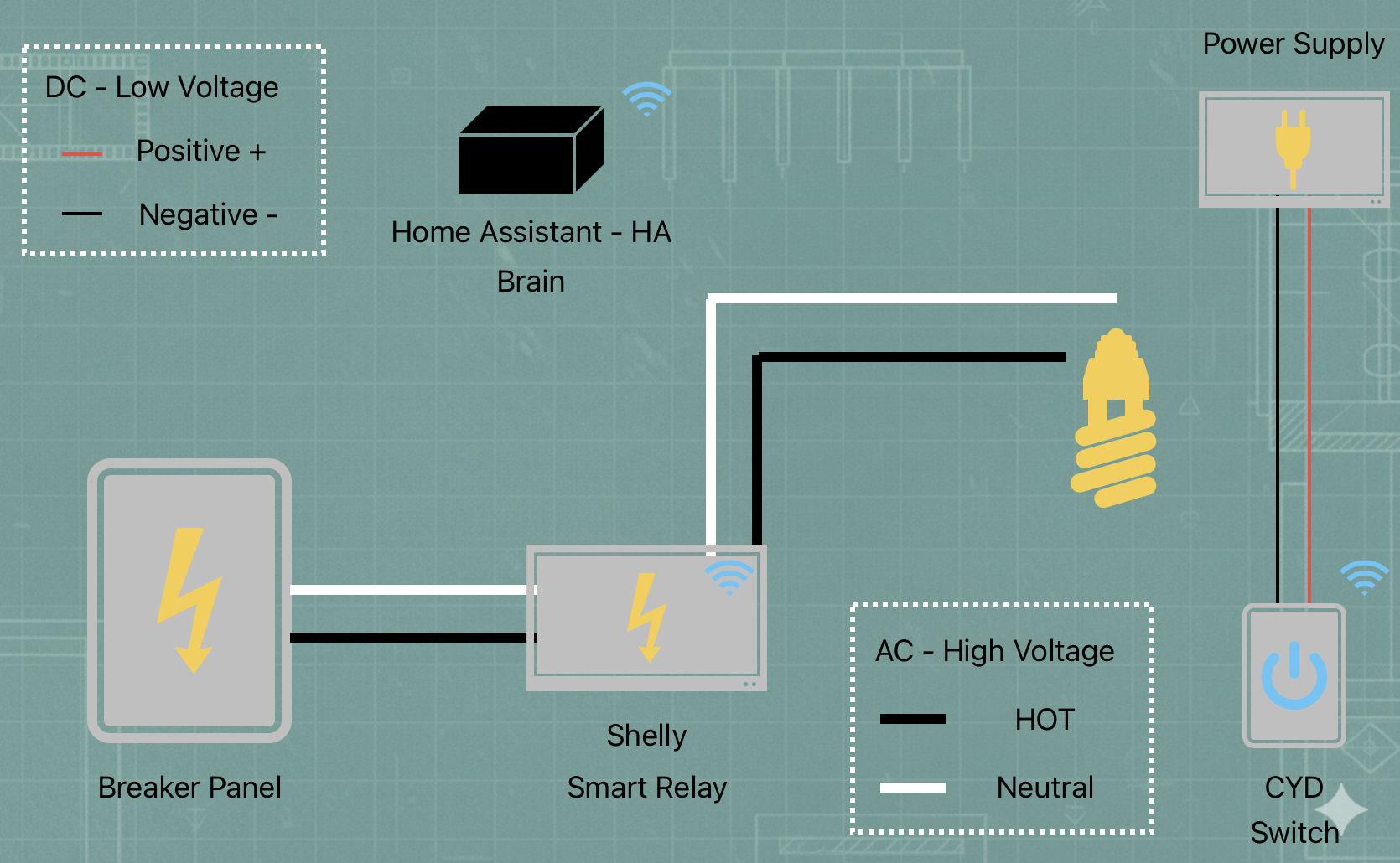
Smart House Diagram
Now, when I tap a button on the CYD touchscreen, the screen sends a wireless message through the house. Home Assistant (the "Translator") hears that message and knows exactly which light I want to turn on. It then sends its own message to a Shelly switch in the electrical panel, telling it to click the power on. Instead of one long wire and one central brain, the devices now talk to each other like people over a radio.
Explain It Like I’m Five
Imagine the house is a busy restaurant, and every light in the house is a meal that needs to be cooked:
- The CYD is the Waiter: He stands at your table with a notepad. He doesn’t cook the food; he just listens to what you want and writes it down.
- The Shelly is the Cook: He stays in the kitchen. He is the only one who can actually turn on the stove and get the job done, but he never talks to the customers. He just waits for a ticket to appear.
- Home Assistant is the Head Chef: He sits in the middle and runs the show. When the Waiter (CYD) brings him a note, the Chef reads it and tells the Cook (Shelly) exactly what to do.
A word on the Power Supply
In the earlier, litetouch diagram, the the Power Supply (PWS) was not included. This made it look like the central computer was magically powering the keypads.
In reality, the old LiteTouch had a power supply connected to it, but I did not see the need to add it to the diagram. Now that I have removed that litetouch central computer, I have to be more explicit about how components get their energy. I use dedicated 5V DC Power Supplies to give the CYD touchscreens the energy they need to stay awake and connected.
I’ve included the PWS in the new diagram above because, without it the "Messenger" (the CYD) wouldn't have the energy to talk to the "Manager" (Home Assistant).
Summary
Out with the Old, In with the New
I created this table to show how I mapped the old functions to the new infrastructure:
| Feature | LiteTouch (Before) | Shelly + HA + CYD (Now) |
|---|---|---|
| Brain | Central Control Unit (Proprietary) | Home Assistant (Open Source) |
| Switching | 6-Channel Dimmer Modules | Shelly Pro DIN-Rail Relays |
| User Interface | Physical Multi-button Keypads | CYD Touchscreens & Mobile App |
| Communication | LiteTouch Data Bus (3-wire) | WiFi |
| Monitoring | None (Blind Switching) | Real-time Wattage & Power Stats |
| Compatibility | Incandescent / Halogen only | Native LED Support |