In-depth LiteTouch Wiring
Legacy Documentation
This page is purely for historical documentation purposes. This information is not strictly necessary to understand how the current system works. However, it provides a vital map of the original infrastructure.
I am including specifics here on how LiteTouch wired individual light fixtures to specific modules and designated breakers. This page is intended as a reference for an electrician in the event of another major overhaul of the system; otherwise, this page can be ignored.
Module/Relays Documenation
The house used two different types of modules/relays:
Dimmer module version 08-2100-01.
The 08-2100-01 is a 6-channel, phase-control dimming station designed for incandescent and magnetic low-voltage (MLV) loads.
It has 6 independent dimming outputs. With 120V AC, and it had a capacity of 20A of total aggregate load.
Limitation: These were designed primarily for incandescent and halogen bulbs. Using modern LEDs on these old modules often caused flickering because the "Dimmer" couldn't handle the low wattage of LED technology.
Relay Module (Model 08-2200-01)
The 08-2200-01 is a 6-channel high-voltage switching station designed for non-dimmable loads.
6 independent relay outputs. With 120V AC. Not sure how much load could it handle, but it was superior to the dimmer module. I think it could handle up to 10A per channel, however I was not able to verify my source.
Power supply
Additionally the system used two power supply Model 08-8620-00. One was located in the bottom left metal box, and it powered the Relay Module (Model 08-2200-01).
The other one was located, next to the Central Control Unit (Brain), in its own metal box, located in the upper left section of the electrical room. Right above the Main Panel breaker. This second power supply powered the Central Control Unit, as well as all the keypad/liteswitches of the house.
Layout
The House used a total of fifteen relays, of which five were Relay Module (Model 08-2200-01), and ten were Dimmer module version 08-2100-01. Here is where the modules were located:
| UPPER LEFT | UPPER RIGHT |
|---|---|
| Module 1 | Module 4.2 |
| Module 2 | Module 5 |
| Module 3 | Module 6 |
| Module 4.1 | Module 7 |
| BOTTOM LEFT | BOTTOM RIGHT |
|---|---|
| Module 12 | Module 8 |
| Module 13 | Module 9 |
| Module 14 | Module 10 |
| Power Supply | Module 11 |
Module 4.1, 12, 13 & 14 were Relay Module (Model 08-2200-01), the rest were Dimmer modules
Wiring Map
This table provides a comprehensive map of the legacy LiteTouch infrastructure. It identifies which circuit breaker feeds each control module and exactly which labeled cables are serviced by those modules.
This information can also be viewed in google doc format, which is more detailed
| Module ID | Feed Breaker(s) | Cable # | Load Description |
|---|---|---|---|
| Module 1 | 28 | 12, 13, 14, 15, 16, 17 | Master Room (Entry, Closet), Hallway, Altar, Room 4 |
| Module 2 | 24 | 6, 7, 8, 9, 10, 11 | Upstairs Living, Hallway, Room 2, Room 1 |
| Module 3 | 32 | 1, 2, 3, 4, 5 | Library (Eye, Balcony), Staircases (Garage & 1st Floor) |
| Module 4.1 | 36 | 18, 19, 20, 21, 22 | Living Room Outlet, Kitchen Desk, Room 1 Outlet, 2nd Floor Bath |
| Module 4.2 | 19 | 38, 39, 40, 41, 42 | Guest Room, Library Hall, Guest Bath, Entrance Bath |
| Module 5 | 23 | 43, 44, 45, 46 | 1st Floor Hall, Dining Chandelier, Outside Main Entrance |
| Module 6 | 40 | 47, 48, 49, 50 | Patio Columns, Pool Area, Dining Table, Semi-Outdoor Room |
| Module 7 | 38 | 51, 52, 53, 54 | Entrance Door Shells, Piano Eye Lights, Speaker Eye Lights |
| Module 8 | 33 | 55, 56 | Entrance Living Chandelier, Patio Hall |
| Module 9 | 29 | 57, 58, 59, 60, 61, 62 | Master Bath (Full Suite), Master Terrace Balcony |
| Module 10 | 21 | 63, 64, 65, 66 | Kitchen (Main Circuits) |
| Module 11 | 35 | 67, 68, 69, 70 | Entrance Chandelier, Outside Gate, Master Terrace |
| Module 12 | 34 | 23, 24, 25, 26, 27 | 2nd Floor Bath Mirror, Room 2 Outlet, Mini Room, Room 3 |
| Module 13 | 26 & 30 | 28, 29, 30, 31, 32 | Library Main, Guest Outlet, Garage, Hidden Living Lights |
| Module 14 | 25 | 33, 34, 35, 36, 37 | Room 4 Bath, Room 4 Closet/Outlet, Master Room Outlet |
Power supply
The power supply located at the Bottom left box used to be fed by breaker 27 and 31. As previouly stated this power supply powered the Relay Modules (Model 08-2200-01)
Unlike the other modules which utilize a single breaker, Module 13 is cross-wired across two breakers to handle higher current demands for the Library and Garage areas: Breaker 26: Services Cables 28, 29, and 30. And Breaker 30: Services Cables 31 and 32.
Video Documentation
This video was taken during the teardown of the LiteTouch system. It shows the original wiring harness and the state of the central control cabinet before the migration.
Legacy LiteTouch Cabinet - Vertical Overview
Photo Documentation
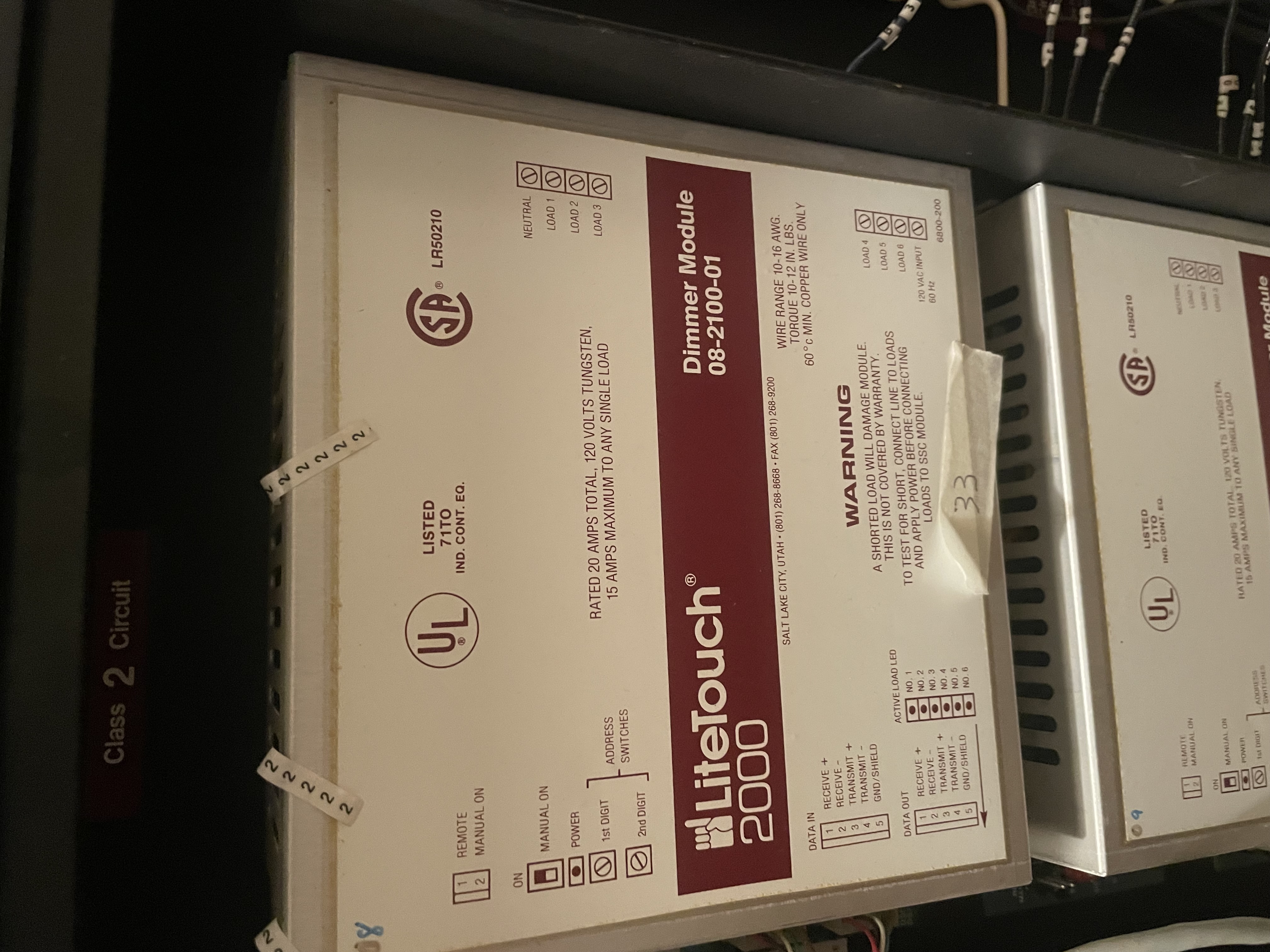
This picture corresponds to Dimmer Module 8, located in the bottom right box.
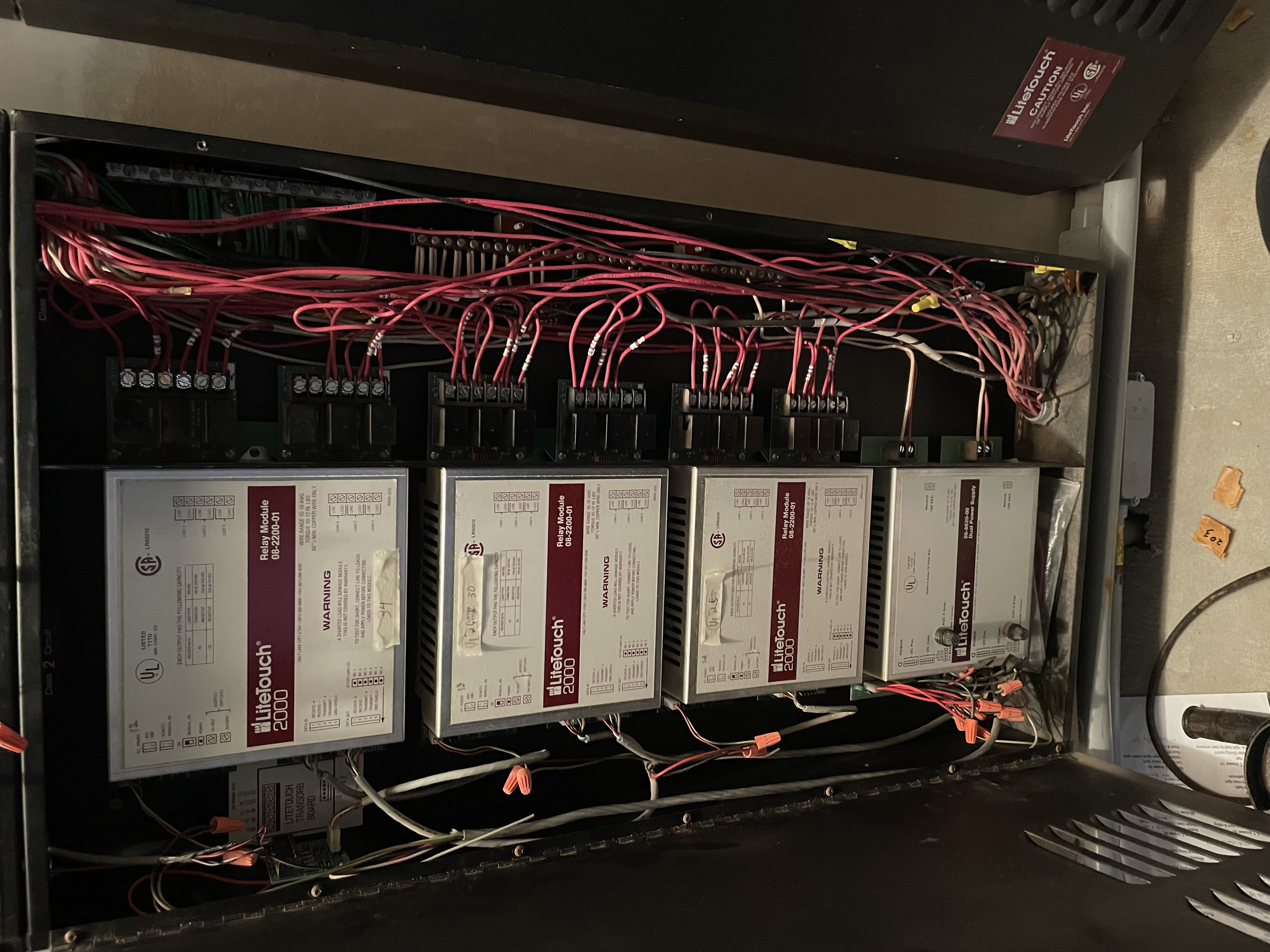
View of the Relay Modules located in the bottom-left quadrant box.
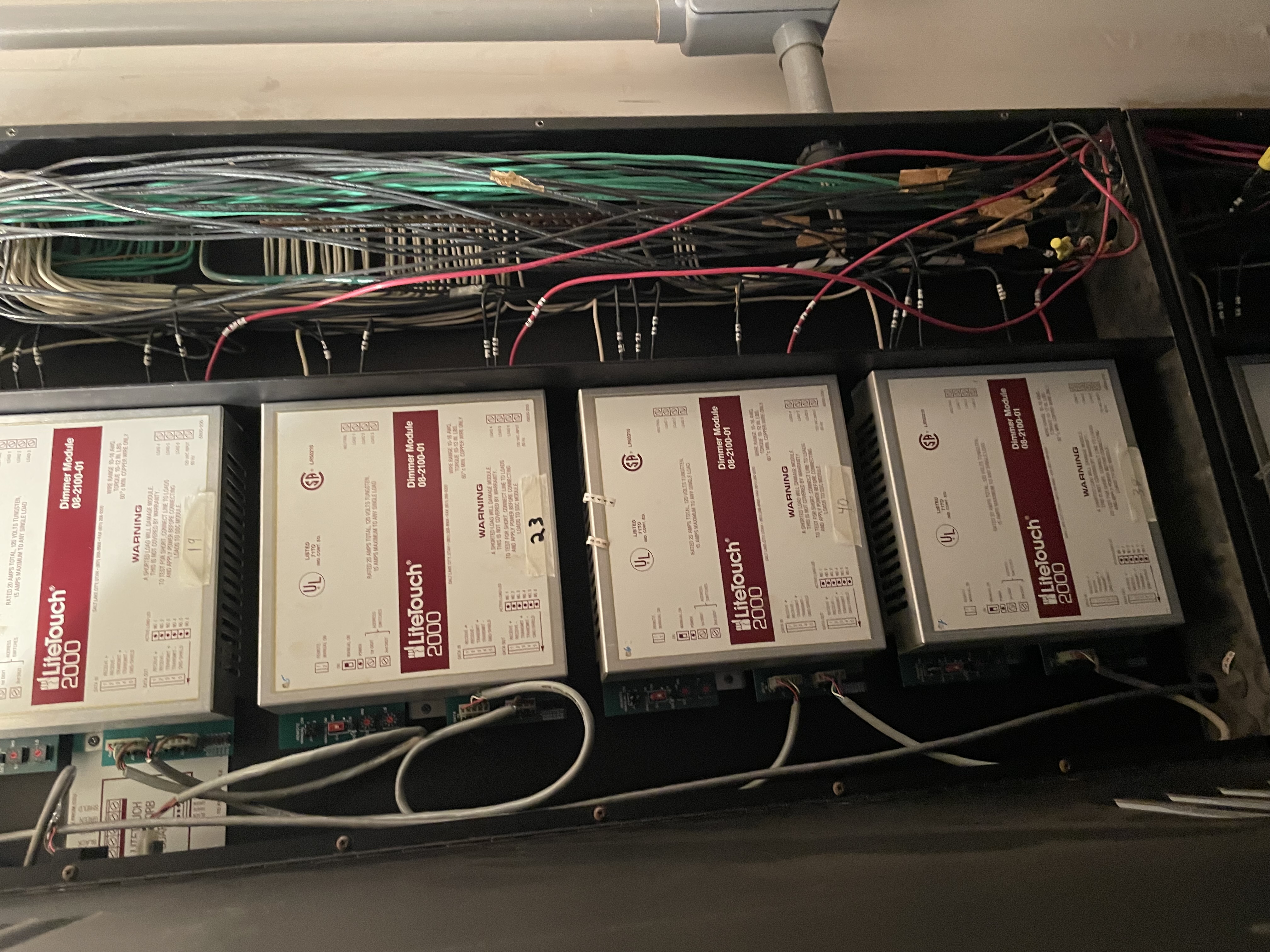
Upper-right quadrant containing Dimmer Modules 4.2 through 7
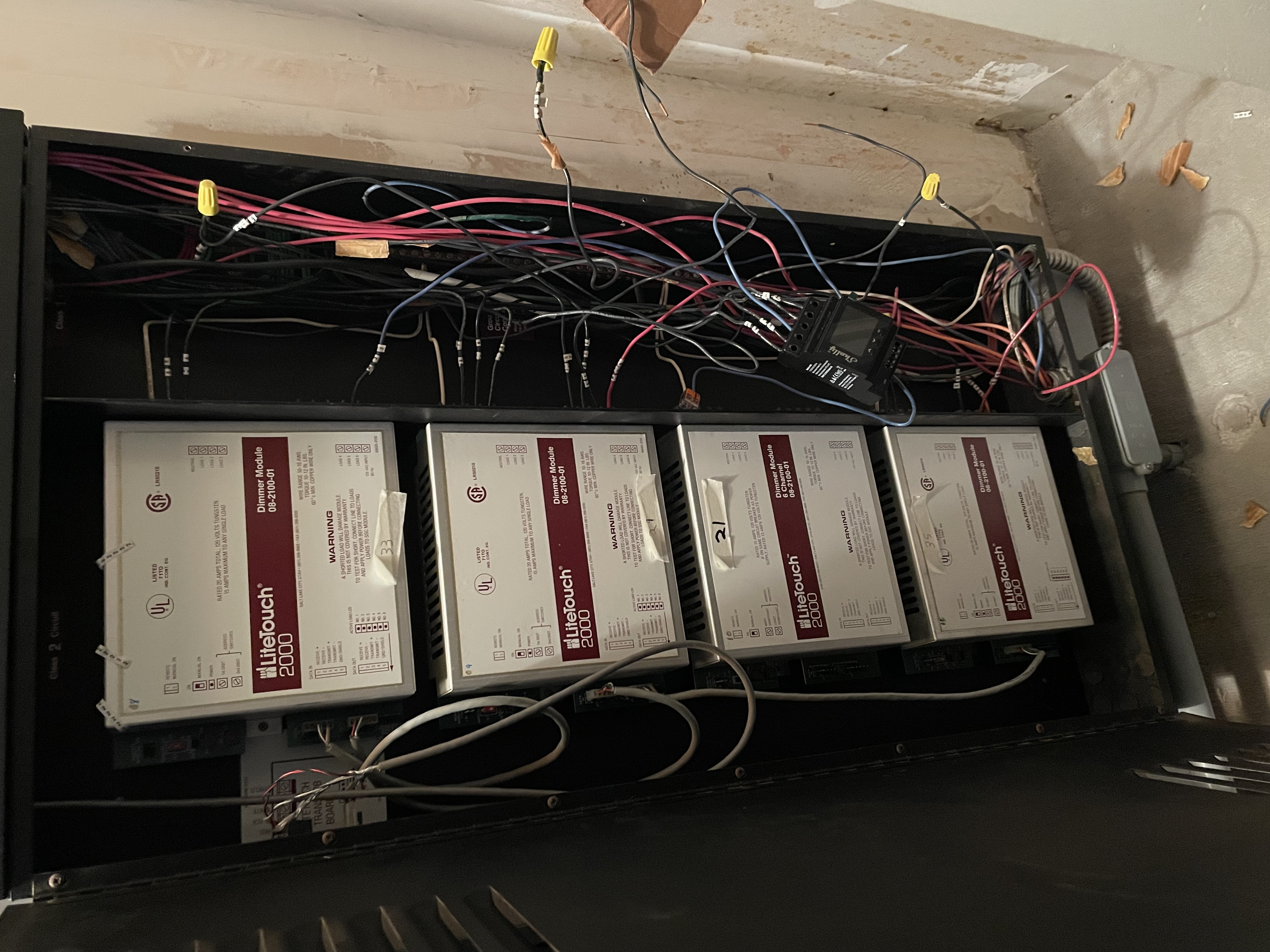
Bottom-right quadrant featuring Dimmer Modules 8-11.
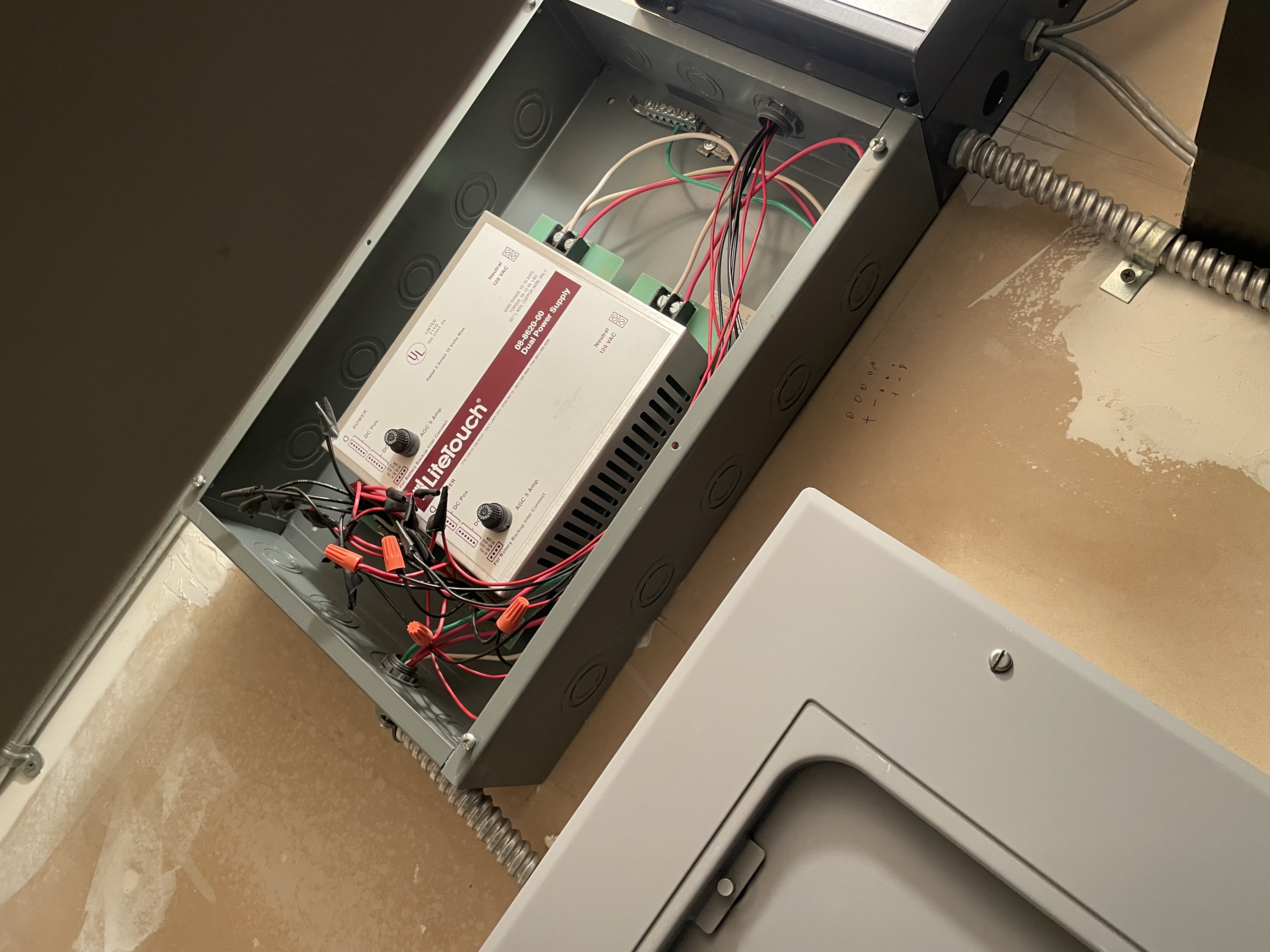
Main power supply providing 24V DC to the LiteTouch keypads and logic brain.